classicretrofit
-
Posts
270 -
Joined
-
Last visited
-
Days Won
1
Content Type
Profiles
Forums
Events
Everything posted by classicretrofit
-
 Yes, definitely send this one back. Can you drop us a line at sales@classicretrofit.com and we will figure it out together. Thanks!
 -
13: Gas Filling, Set Up and Test
classicretrofit replied to Jonny Retrofit's topic in Electric Air Conditioning
test details to follow -
Parts List: For RS stock numbers listed - please go to uk.rs-online.com Photo Description Mfr Part Number RS Stock Code PFL PCB Case Deutsch EEC-325X4B 724-2557 Contactor (optional): 12V Extra Heavy Duty Make/Break Relay - 120A Albright Engineers SW60-360P n/a DTM Series, 12 Way Plug Connector, with Crimp Termination. Grey Deutsch DTM0612SA 724-2576 DTM Series, 12 Way Plug Connector, with Crimp Termination. Black Deutsch DTM0612SB 724-2579 DTM Series Wedge Lock For Use With 12 Way Plug Deutsch WM12S 724-2573 0462 Crimp Contact, Female, Crimp, Nickel Plating 20 - 24 AWG Deutsch 0462-201-20141 425-822 Crimp Tool DT Series, HD10 Series, HD30 Series, HDP20 Series, 20 → 12 AWG Wire Size HDT-48-00 425-973 Uninsulated Tin Plated Tubular Ring Terminal, M5 Stud Size, 16 mm² RS Pro 122-5002 Uninsulated Tin Plated Tubular Ring Terminal, M6 Stud Size, 16 mm² RS Pro 531-043 100A Midi fuse holder Littelfuse 04980921GXM5

-
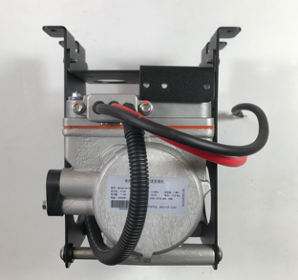
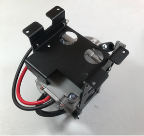
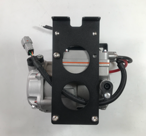
10b: Compressor Bracket Assembly RHD
classicretrofit replied to classicretrofit's topic in Electric Air Conditioning
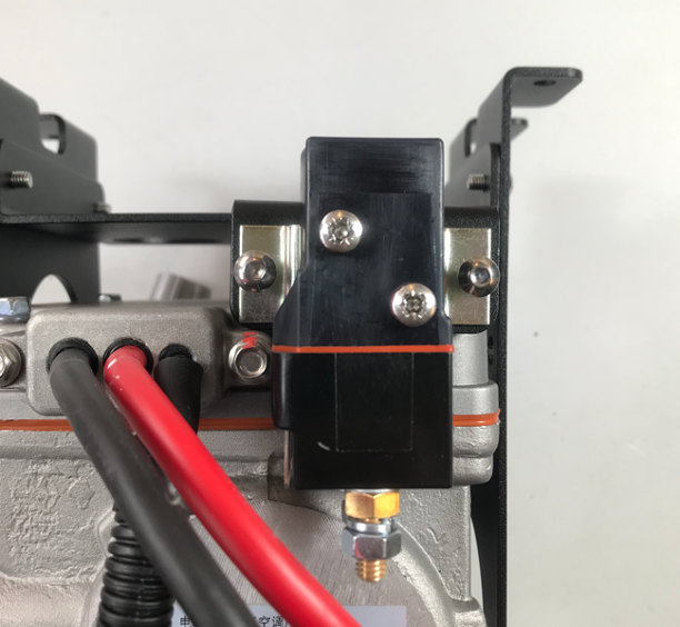
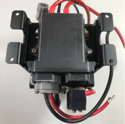
Bolt the ECU housing onto the top of the compressor. Note that the ECU is positioned so that the cables exit at the opposite side to those exiting the compressor. Assemble the red power post and the relay onto the relay plate with M5 and M6 bolts into the tapped holes. The metal work may need an extra M6 tapped hole on early versions. Bolt the red compressor power cable and the red ECU power cable (the one with the red rubber boot) to the power post. Slide the rubber boots over the terminals and dress neatly. Attach the other red ECU power cable to the separate heavy duty red cable in the wiring kit via the 80A fuse holder. Note that the separate cable has an M5 terminal to connect to the fuse, and an M6 terminal at the other end to connect to power. Do not forget to add the fuse, then click the black cover into place. Place the red shrink-wrap over the fuse holder and heat to shrink and make a waterproof seal. The Compressor pre-assembly is now complete.
-
10b: Compressor Bracket Assembly RHD
classicretrofit replied to classicretrofit's topic in Electric Air Conditioning
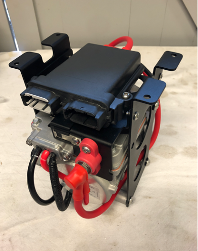
Lay out the parts required for the compressor side cheeks, and ECU/Relay mounting brackets. Use Nylon washers under the heads of the M8 bolts, and 2 nylon washers between the left cheek plate and the threaded spacer. Install the right cheek first, and thread the long bolts into the threaded spacers. Then route the control cable as pictured, and install the left cheek. Finally, tighten all fixings.
-
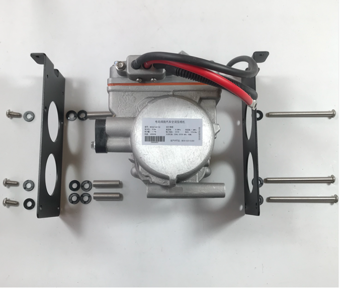
Locate all components in the picture (ECU will be pre-assembled). COMPRESSOR PARTS LIST 12V Compressor 1 M6*20mm Button Head 2 Electrocooler ECU in housing, with tails 1 M5*10mm Button Head 1 RHD Compressor Side Cheek 2 Relay Plate 1 Relay 1 M8 Nylon Washer 12 M8*16mm Button Head 3 M8*100mm Button Head 3 M8 35mm Spacer 3
-
10a: Compressor Bracket Assembly LHD
classicretrofit replied to classicretrofit's topic in Electric Air Conditioning
Install the contact relay on the end tab of the ECU plate (see further down for power post install option) Feed the ECU-Contactor power cable through the right side of the compressor. Bolt the ECU housing onto the ECU plate. Bolt the compressor power cable and the ECU power cable to the contactor. The contactor provides isolation from the battery for safety and protect against parasitic current draw from the compressor. Note that some kits also come with an option of a direct connection using a power post. This is typically only used in a racing application where a battery isolator is fitted. Slide the rubber boots over the terminals and dress neatly. The compressor module assembly is now complete.
-
10a: Compressor Bracket Assembly LHD
classicretrofit replied to classicretrofit's topic in Electric Air Conditioning
Lay out the parts require for the compressor side cheeks, and ECU/Relay mounting brackets. Use Nylon washers under the heads of the M8 bolts, and 2 nylon washers between the left cheek plate and the threaded spacer. Install the right cheek first, and thread the long bolts into the threaded spacers. Then route the control cable as pictured, and install the left cheek. Before tightening any of the M8 bolts, install the ECU plate with the M5 bolts. Finally, tighten all fixings.
-
Assembling compressor brackets Tools and Equipment Required Flat ended T handle hex key set (2.5mm, 3m, 5mm). Do not use ball end hex keys. Hydraulic Crimper 7mm Spanner or socket Assembly of Compressor module – LHD Locate all components in the picture (ECU will be pre-assembled). COMPRESSOR PARTS LIST 12V Compressor 1 M6*20mm Button Head 2 Electrocooler ECU in housing, with tails 1 M5*10mm Button Head 5 LHD Compressor Side Cheek 2 ECU/Relay Plate 1 Relay 1 M8 Nylon Washer 12 M8*16mm Button Head 3 M8*100mm Button Head 3 M8 35mm Spacer 3
-
06a: Blower installation (LHD)
classicretrofit replied to Jonny Retrofit's topic in Electric Air Conditioning
The restrictor is designed to let some fresh air in to the vehicle. In very hot conditions, a complete blank of the cowl vent may be necessary. Finished blower and duct work install (LHD)
-
06a: Blower installation (LHD)
classicretrofit replied to Jonny Retrofit's topic in Electric Air Conditioning
On cars with centre vents, the passenger side inlet duct must route over the screen duct. Easier to remove the top of the blend valve. RHD shown, on a LHD the squashed tube will be on the left. Screen duct refitted. 60mm recirculation duct runs between the ‘T’ and blower inlet. Cut to length and connect the 40mm side vent ducts to blower. Connect the front lower outlets to the heat blend valves with 60mm duct and secure. On cars with centre vents connect the top outlet to the fresh air funnel. Block off all unused air outlets (60mm cap provided). Connect the original Bowden cable to the new blower using the nuts, bolt and clip from your old blower. The Bowden cable needs to be re-routed in order to reach the new lever. We suggest a cable tie round the front of the clip too. Plug in the electrical connector. Please note that plug must not be connected the wrong way or damage may occur to the internal resistor pack in the blower. The cable from the plug exits downward. Connect the battery temporarily and test blower at all three speeds. Check for air leaks and outlets that you forgot to cap off. Finally, fit the air restrictor gasket behind the cowl vent and refit the original mesh and trim piece.
-
06a: Blower installation (LHD)
classicretrofit replied to Jonny Retrofit's topic in Electric Air Conditioning
Best angle of attack for install. Once under the cowl, rotate top forward to locate scoop. The scoop is a tight fit to the body so push on the ends of the scoop to ease it on. No seal/gasket required. Starting at the rear of the blower cut the 60mm recirculation ducts (from the ‘T’ branch) to length and secure to the blower. On cars with central vents, on the passenger side, the 60 duct must be squashed slightly and fed over the short duct to the screen vent. On the scuttle panel, there is tab which was used to attach the scuttle support stay. It has an M6 thread. This can be bent towards the front of the car so that it is parallel to the top of the blower. Screw in an M6 rubber foot so that it rests on the top of the blower to provide support for the scuttle panel.
-
06a: Blower installation (LHD)
classicretrofit replied to Jonny Retrofit's topic in Electric Air Conditioning
Fit new blower On LHD vehicles with brake servos/boosters the A/C refrigerant hoses when installed are very close to the brake warning light switches. It can be prudent to make up and connect the hose ends at the expansion block, prior to blower install. The blower can also be offset left and right by loosening the four screws visible in the scoop. There is a 7mm nyloc nut on the back which can be reached through the hole in the stainless bracket. Best to do this out of the car Prior to fitting the blower, fit the sense wire for the rear screen defogger or any other high current circuits. Identify the rear demist switch and find the terminal that goes live when the defogger is on. Using a piggy back spade, connect a wire (2m should be sufficient) here for use later. Make sure that the blower drain tube is fitted to the correct side for your vehicle. Find the blower electrical plug so it is not lost behind the blower when installed. Connect it to the new blower before the ductwork gets installed. (It is worth doing a test of the blower on all three speeds at this point). Remove the plastic protective cap from the evaporator and attach the expansion block using the 2 x M5 cap head screws. Use a little PAG oil on the o-rings. Make sure that, on vehicles with central vents, the plastic vent funnel is correctly positioned before installing the blower. There is a small tab on the body for securing this part and its duct with a hose clip. It is annoying if it comes off after the install so make sure it is secure. Now that the ductwork is connected but not trimmed, offer up the new blower. It is a tight fit and there is a certain knack to getting it in! Lay the blower on its back and put the driver’s side in first, then rotate the top forward into the scuttle vent opening. Secure the blower using the two screws through the vent opening as per the original. You can use either side drain hole or both. There is a blanking cap in the pack. Either drain into the original tube or through the steering rack cavity. Unfortunately, we couldn’t make the drain tubes exactly line up (our tube needed to be at lowest point) so an ‘S’ bend may be required. -
06a: Blower installation (LHD)
classicretrofit replied to Jonny Retrofit's topic in Electric Air Conditioning
Side / Auxiliary vent variations The new blower has a 40mm spigot either side for supplying air to side vents where fitted. Over the years, Porsche used many different sizes of hose for the side vents. We chose 40mm as it is adequate for airflow. Connection to existing hose or body tubes can be accomplished through wrapping the duct/tube in neoprene tape to get an air tight seal. On an SC, there are two metal tubes welded into the body that supply air to the side vents. The tubes are actually less than 40mm. Wrap a length of neoprene tape around the tube to make it up 40mm in diameter. Push on the 40mm duct and secure with a cable tie or a hose clip. On a 3.2. Carrera or Turbo, and A/C cars, locate side vent hose and use the neoprene tape to connect the 40mm hose into the existing hose. Wrap with duct tape. On cars without centre vents, the 40mm spigots can be used for supplementary cooling as required. Route as you see fit. -
06a: Blower installation (LHD)
classicretrofit replied to Jonny Retrofit's topic in Electric Air Conditioning
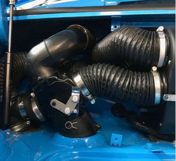
‘T’ piece in place with branch that will run to rear inlet of new blower. This is the ‘easy’ side. ‘T’ piece in place on a LHD car. The top hose on the right is for the centre vent, the T branch connection at the blower is hidden behind it. When you have completed the two sides, position the new inlet ducts so that they are not fouled by the hood/trunk hinges. You will find they might have to squash a little but this is ok.
-
06a: Blower installation (LHD)
classicretrofit replied to Jonny Retrofit's topic in Electric Air Conditioning
Note: the photos below show a RHD install. On LHD vehicles, the centre vent feed is on the other side. To complete the duct work there are a number of connections that have to be made in the luggage bay. There is a lot of duct to fit in a small area. You will find that one side is more cramped and it can be a lot easier to remove the whole blend valve. Two screws under the dashboard saves a lot of aggravation. The following photo sequence adds some detail. Passenger side (RHD) showing how the T piece should sit. It can help to reroute the harness and trim back the end of the T piece that will face the blend valve. This is an SC so we have to get the small hose on to the metal through body tube. Easier to get the small hose on first and secure. Use neoprene tape on the inside of the duct to make up the difference in diameter before fixing, then go for the 60mm inlet duct. And finally, get the blend valve back in place. Short 60mm hose connection between T and blend valve is hidden in this photo.
-
06a: Blower installation (LHD)
classicretrofit replied to Jonny Retrofit's topic in Electric Air Conditioning
Bottom side and top side of same 60mm duct and T piece
-
06a: Blower installation (LHD)
classicretrofit replied to Jonny Retrofit's topic in Electric Air Conditioning
Addition of recirculation The aim is to insert a ‘T’ branch each side into the 60mm duct that runs between each heat blend valve and the heat source in the footwell sill/rocker. The ‘T’ piece provided should sit just above the opening to the footwell, but still in the luggage bay. The branch of the T will provide the recirculation function to the inlets at the back of the new blower. [Note: Up to and including the SC, this is a single piece of duct, On the 3.2 Carrera, there is a blower either side in the footwell.] From the top side (in luggage bay), loosen the 60mm hose clips from the left and right side heat inlet ducts (the ones that disappear through the rubber seal into the footwells) From inside the car, remove the floor mats and fold back carpet from side of footwells to expose the other end of the same 60mm heat duct. Remove the heat duct. On 3.2 Carreras, the footwell blowers may also be removed as the new blower assists drawing heat from the engine although not as much as the footwell blowers to be fair. Whether it is advisable to also remove the engine blower is down to personal preference. How hot do you like it? Replace the removed duct piece with a slightly shorter 60mm pipe, run this from the lower sill/rocker tube in the footwell to opening in the firewall. From the top (inside the luggage bay) insert the 60mm ‘T’ piece as the hose passes through the firewall rubber seal so that the ‘T’ sits just topside of the firewall. -
06a: Blower installation (LHD)
classicretrofit replied to Jonny Retrofit's topic in Electric Air Conditioning
With old blower removed, identify holes for cabin wiring and wire sense lines to high power accessory switches. Attaching a ‘piggy back’ sense wire to the rear defogger switch. This tells the A/C to cut back on power if this is switched on.
-
06a: Blower installation (LHD)
classicretrofit replied to Jonny Retrofit's topic in Electric Air Conditioning
Removal of Existing Fresh Air Blower Remove the large centre section of carpet from the front luggage bay to expose the cardboard blower cover. Locate the screws for the cover and remove. Remove also the scuttle support bracket to gain access to the fresh air blower. Please note the blower cover cannot be refitted when the new A/C blower is installed. The carpet, however, should still fit back into place without the cover installed. Undo the 4 air intake screws on the scuttle mesh and remove to gain access to the blower plenum fixing screws – undo these and remove. Disconnect the 60mm hose clips that connect to the blower and remove the hoses. Undo the Bowden cable nut and clip and detach Bowden cable. Pull the lower part of the blower plenum forward and remove the drain hose underneath. Disconnect the electrical plug and remove the complete blower unit and plenum from the car. Remove the plastic steering column cover (two push fixings towards the rear). The bottom of the new blower is deeper than the original so the cover will either need notching or cutting into two halves. You now should have good access to the bulkhead. Some things to do when you have access to the bulkhead area: • Identify an access hole to the cabin and run A/C control switch loom • Wire in the sense line for any high current accessories (e.g. wiper and rear defogger) • Make sure that heat vent sliders are working and adjusted correctly. Two of the cables are on the back of the blend valves and cannot be reached once the blower is in. • Replace the intermittent wiper relay if your wipers don’t park! -
06a: Blower installation (LHD)
classicretrofit replied to Jonny Retrofit's topic in Electric Air Conditioning
CAD model of the new blower unit with evaporator and fan inside The new blower still uses the existing blend valves (the two black parts with the cables attached) but modifies their function to facilitate recirculating cabin air. With the revised scheme, the hot air outlet into the footwell becomes an inlet. The new blower has inlets at the rear, allowing air to be extracted from the footwell area. A/C cooled air is pushed out into the cabin and drawn back into the blower via the footwells, creating an effective air flow circuit. We have made it as simple as possible to re-duct the front of the car, but it can be fiddly. Hopefully we have laid these instructions out in an order that will prevent any rework. Please use the forum to ask questions or share install tips!
-
Pipework fitting identification The following graphic is to aid identification of the pipework fittings. The actual number of items, such as the blue plastic clip fitting guides, may vary in your kit.
-
11: Hoses and Fittings
classicretrofit replied to Jonny Retrofit's topic in Electric Air Conditioning
Pipework fitting identification The following graphic is to aid identification of the pipework fittings. The actual number of items, such as the blue plastic clip fitting guides, may vary in your kit.
-
For those using our half kit, you do not have to install our cabin button. You can use the factory blower switch to turn on the AC. This requires wiring the orange wire in our loom to the red/white wire on the factory blower 4 pin connector. Installation of the half kit requires changing settings in the ECU. Please see our Setup and Test Guide.
-
Appendix 1: Carrera 3.2 Fog Lamp Porsche started to recess the foglights into the valance for the Carrera 3.2 models. Unfortunately, the foglight assemblies are quite deep so there is a clash with the front of our condenser. We haven’t got a kit to solve this right now but here is what we did on a recent 3.2 install. Not much space for the foglight in here. Back of foglight bracket has been removed. We dropped the right side of the valance down and removed the bracket as marked. I know, it’s painful but valances are cheap panels and not part of the main shell. We then removed the back of the foglight and made up this folded bracket. We then attached it to the remaining lip of the valance. The end result is: Although the ‘fake’ foglight doesn’t notice when on the car, We are currently looking out for a small LED DRL unit to fit (to both sides). If you have any bright ideas, let us know!!